Mining Lift Hook
Dam Gate
.Conveyor Chain
Cable Short
Description of Finite Element Analysis
Finite Element Analysis (FEA) is a software tool used for structural analysis – providing an accurate prediction of how a component (or a complex assembly) responds under various types of loads (such as mechanical force, thermal / transients and vibration).
Structural analysis includes all types of steady or cyclic loads, mechanical or thermal. Thermal analyses include convection, conduction, and radiation heat transfer, as well as various thermal transients and thermal shocks. Finite element analysis is used to analyze a wide variety of components for all types of loads including mechanical, vibratory, seismic, heat transfer, electromagnetics, and fluid flow.
FEA software is readily available and is commonly used in engineering design & analysis. The engineer using FEA should be experienced with engineering mechanics and finite element analysis principles – as well as understand the requirements of various Codes including ASME.
Development of FEA began in the 1940’s, and by the 1950’s it was used by aerospace engineers to design better aircraft structures. Since then, aided by the rapid growth of computing power, the method has continually developed, and is now the tool of choice for analysis by mechanical, civil, biomechanical, and other engineers. Read more about the History of Finite Element Analysis.
FEA is used to analyze complex geometries, whereas very simple ones (for example, a beam) can be analyzed using hand calculations. For a structure subjected to a load (thermal, mechanical, vibratory, etc.) its response (deflection, stress, etc.) can be predicted and measured against acceptable defined limits. This allows engineers to easily spot areas of vulnerability and run studies to correct structural issues.
Typically, acceptable limits are defined by a factor of safety – which is the ratio of the stress in a component, to the allowable stress of the material. If the factor of safety is too small, the possibility of failure becomes unacceptably large; on the other hand, if the factor is unnecessarily large, the result is a uneconomical or nonfunctional design.
For the majority of structural and machine applications, factors of safety are specified by design specifications or codes written by committees of experienced engineers, such as the American Concrete Institute (building codes requirements for reinforced concrete) or the (ASME) American Society of Mechanical Engineers (codes for pressure vessels, heat exchangers, and other process equipment).
Read more about the History of the ASME Code.
How FEA is performed
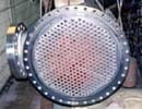
Shown here is a heat exchanger.

Since the heat exchanger has symmetry, only a slice needs to be modelled.
Instead, all the equations from all the elements over the entire structure need to be solved simultaneously. This task can only be performed by computers. It is noteworthy that, as the structure is broken into a larger number of elements, a greater number of simultaneous equations need to be solved. Thus, typically, results for more complex structures require more computing power.
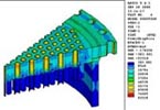
Whenever possible, symmetry is used to minimize model complexity. Typically finer meshes are used in the locations where the highest stress or heat flow may exist, allowing quicker solutions to what would otherwise take longer computation time. Finite element analysis is often used to verify design integrity and identify critical locations on components without having to build the part or assembly – and provides results that define areas of high strains/stresses which may or may not be life-limiting to the component.
Shown here is a temperature distribution model of the heat exchanger.
References
1) “Finite Element Analysis – Theory and Application” S. Moaveni, Prentice Hall, 1999
2) “An Introduction to the Finite Element Method” J.N. Reddy, McGraw Hill 1993
3) “Building Better Products with Finite Element Analysis” V. Adams & A. Askenazi, Onward Press, 1999
FEA Related Resources
– Ansys Software
– NAFEMS: International Assoc. of Engineering Modelling, Analysis and Simulation
O’Donnell Consulting provides comprehensive Finite Element Analysis to ensure component structural integrity and compliance to Codes including API, AWS and ASME. We’ve performed structural analysis, design optimization, CFD, thermal, stress, vibration and fatigue analysis for clients in industries including energy, mining, and petrochemical. Typical clients include:
- Companies that may have FEA analysis capabilities – but require assistance to meet a deadline.
- Companies that require an independent engineering review or a Fitness-For-Service.
- Manufacturers with clients who require stress, thermal, or vibration analyses to confirm structural integrity and compliance to specific Codes.
- Fabricators and/or owner/operators that wish to perform a failure investigation – determining the root cause, and developing improved, safer designs.
- Owner/operators and their representatives that wish to perform a failure investigation to determine liability.
Summary of Benefits of FEA
- Graphical software tool that displays stresses, strains and displacements
- Pinpoints design deficiencies
- Virtual prototyping
- Efficient and less expensive design cycle – increasing productivity and profit.
- Used to quantify stress, vibration, fatigue, buckling
- Used to ensure structural integrity to Codes as API & ASME
- Can be used to distinguish between failures due to design deficiencies, materials defects, fabrication errors, and abusive use
- It provides quantified results previously based on metallurgical and mechanical testing
- It provides excellent visual aids and animations easily understood by juries
Historical Note: Early FEA code development followed hardware progress. ANSYS was first released in 1970, running on $1,000,000 CDC, Univac, and IBM mainframe computers – which were much less powerful than today’s PC’s. A Pentium PC could solve a 5,000 x 5,000 matrix system in a few minutes, instead of days as in the past.
We have successfully used finite element analysis to evaluate the structural integrity of equipment, as well as in supporting litigation in State, Federal, and International courts.
For examples of our engineering and legal cases, see Portfolio.
For a partial list of components we have worked on, see Industries Served.
Learn from the experience of others. Especially when one such “other” is Dr. William O’Donnell, PhD, PE, Founder and President of O’Donnell Consulting Engineers, Inc., and ASME “Engineer of the Year” – his 50 years of experience in analysis of components including fatigue and fracture safety evaluations and failure analyses are now comprised in this volume.
If you are interested learning more in Engineering Design, Manufacturing and Construction, as well as Failure Analysis, then this book is a must have!
$49.95*
* Does not include shipping, handling or tax