From Rayleigh-Ritz to ASME Code Compliance: The History of Finite Element Analysis
Summary
In the 1870’s, a British physicist named John William Strutt — better known as Lord Rayleigh — was working on a problem that had nothing to do with engineering software: he wanted to predict the natural frequency of a vibrating structure without solving the full differential equations of motion. His solution was to assume a plausible deformed shape, then minimize the total energy distributed across that shape to find the most probable response. It worked. Walter Ritz later extended the approach into a generalized method for predicting displacement and stress in structures — what engineers now call the Rayleigh-Ritz Method.
Neither man could have anticipated that this mathematical framework, developed to describe the vibration of bells and membranes, would become one of the foundational algorithms of modern structural analysis. But the essential idea — discretize a continuous problem into manageable pieces, apply energy principles, solve — is precisely what finite element analysis does today on every pressure vessel, piping system, and structural component that passes through an engineering firm’s analysis software.
O’Donnell Consulting has been performing FEA-based structural analysis since the early commercial era of the technology — applying methods that trace directly to the foundational work described below. Understanding where FEA came from is not merely historical context. It illuminates why the method works, where its assumptions are embedded, and when experience matters as much as software.
Numerical Methods and the Limits of Analytical Solutions
The Rayleigh-Ritz Method proved too cumbersome for geometrically complex structures — the number of candidate shape functions grew exponentially as complexity increased, making hand calculation impractical beyond simple cases. Through the 1930’s and early 1940’s, engineers working on aircraft structures, bridges, and hydraulic systems were reaching the limits of what closed-form analytical solutions could reliably handle.
By the 1940’s, a parallel track of development was underway in applied mathematics. Alexander Hrenikoff developed lattice-based approaches for framing and truss structures. Alberto Castigliano’s energy theorems — developed decades earlier — were being systematically applied to structural problems. William Rowan Hamilton’s principle of stationary action provided the variational foundation that would later underpin finite element formulations. In 1942, Richard Courant published a paper proposing that a continuous domain could be divided into triangular subregions, with a piecewise linear function approximating the solution within each triangle. The paper attracted little attention at the time. Its significance would only become clear a decade later.
Digital Computing and the Birth of Finite Elements
The same decade that produced Courant’s triangular subdivision paper also produced ENIAC — the Electronic Numerical Integrator and Computer, unveiled at the University of Pennsylvania in 1945 and commissioned by the U.S. Army to calculate ballistic trajectories during World War II. ENIAC used vacuum tubes throughout for both calculation and switching, operated at a maximum speed of approximately 5,000 additions per second, and required a dedicated team of operators to manage its 18,000 vacuum tubes and 6 million hand-soldered connections. It was not a tool anyone would use for structural analysis. But it demonstrated, for the first time, that a machine could perform the kind of iterative numerical computation that structural problems required.
By the early 1950’s, analog computers had been developed to handle more complex structural problems, and the promise of digital machines was beginning to attract serious engineering interest. With more powerful hardware becoming conceivable, analytical methods advanced to include matrix-based solutions for frame and truss structures — the direct precursor to modern finite element stiffness matrices.
In the 1950’s, Boeing engineers began using triangular stress elements — directly implementing Courant’s idea — to model the behavior of airplane wings under aerodynamic loading. The structural complexity of swept wing designs had simply outpaced what rule-based methods could address. The triangular element gave them a way to approximate stress distributions across a continuous surface using a finite number of discrete regions. The approach worked, and major aerospace manufacturers began developing in-house programs to extend it.
In 1956, Turner, Clough, Martin, and Topp published “Stiffness and Deflection Analysis of Complex Structures” in the Journal of Aeronautical Sciences — the first formal paper describing what would become the finite element method. Four years later, in 1960, Ray Clough coined the term “finite element” at an ASCE conference in Pittsburgh, giving the technology a name that has been in continuous use ever since.
Commercialization: NASTRAN and the First Software Era
The 1960’s brought digital computers powerful enough — thousands of operations per second — to make commercial FEA viable. Most codes through this period were still industry-specific or even company-specific: programs developed for airframes didn’t transfer readily to pressure vessels or civil structures. Zienkiewicz and Cheung wrote the first textbook devoted entirely to the finite element method in 1967, establishing the theoretical framework that allowed the method to generalize across engineering disciplines.
The turning point for broadly applicable FEA came when NASA awarded a contract to a small analog computer manufacturer serving the aerospace industry — The MacNeal-Schwendler Corporation — to develop a general-purpose FEA code. The result was NASTRAN: a program designed from the outset to handle structural problems across industries, not just aircraft. Its original architecture imposed a limit of 68,000 degrees of freedom, a constraint that seemed almost impossibly generous at the time. When the NASA contract concluded, MSC continued developing MSC/NASTRAN commercially while the original government-funded code became publicly available. Parallel commercial developments during the same period produced ANSYS, MARC, and SAP — programs that remain in use today in forms their original developers would barely recognize.
Computing power through the late 1960’s and 1970’s remained a practical constraint. Minicomputers were more powerful than earlier mainframes, but building and solving large finite element models was still resource-intensive enough to limit FEA to specialists with institutional access to computing infrastructure. The method existed; routine use did not.
Graphics Processing and the Integration of FEA into Engineering Practice
The shift that brought FEA into mainstream engineering practice was not a breakthrough in numerical methods — it was the development of graphical pre- and post-processors in the 1980’s. Before graphical interfaces, FEA output meant studying tables of nodal displacements and element stresses — dense numerical output that required significant expertise to interpret. The introduction of color stress contour plots fundamentally changed how the results were interpreted. Stress concentrations that had previously required careful manual extraction from tabular data became immediately visible as color gradients on a screen.
This visual interpretation transformed FEA from a specialist calculation tool into a design engineering tool. For the first time, design engineers — not just analysis specialists — could incorporate FEA results into an iterative product development process. Geometry changes could be evaluated quickly, stress hot spots identified early, and designs optimized before physical prototypes were built. The cost of the analysis dropped below the cost of the design iterations it replaced.
For pressure vessel and piping engineering specifically, this era marked the beginning of FEA’s integration into ASME code compliance work. As the method became more accessible, the ASME Boiler and Pressure Vessel Code began explicitly accommodating — and eventually requiring — FEA for complex geometries and loading conditions that handbook formulas could not reliably address. Design by Analysis under ASME Section VIII Division 2 is, at its core, a codified framework for applying FEA to pressure equipment in a defensible, failure-mode-specific method
Modern FEA: Capability, Scope, and What Experience Adds
Contemporary FEA software bears little surface resemblance to NASTRAN’s 68,000-degree-of-freedom architecture. Modern solvers routinely handle models with tens of millions of elements, running on parallel computing clusters or cloud infrastructure. Adaptive mesh refinement automatically concentrates element density at stress concentrations. Higher-order element formulations capture curved geometries and nonlinear material behavior that first-generation triangular elements approximated crudely. Multi-physics coupling allows simultaneous solution of thermal, structural, fluid, and electromagnetic problems within a single model.
These capabilities matter for pressure vessel engineering specifically. Thermal fatigue analysis requires accurate temperature distribution as the input loading to a structural model — a coupled thermal-structural problem that earlier generations of FEA could only approximate sequentially. Creep analysis at elevated temperatures requires material models that update incrementally as stress redistributes over time. Buckling analysis under external pressure — critical for vacuum vessels and submerged equipment — requires nonlinear geometric formulations that linearized first-generation elements did not support.
What software capability does not replace is engineering judgment about how to build the model, what boundary conditions actually represent the physical situation, and how to interpret results in the context of code requirements and failure mechanisms. The history of FEA is also a history of errors made by capable engineers using correct software on incorrectly framed problems. Mesh density, element type selection, contact definition, load application, and results interpretation all require experience that no solver provides.
O’Donnell Consulting has been performing FEA to ASME, API, and industry codes for over 30 years — across pressure vessels, piping systems, power generation equipment, aerospace components, and forensic investigations. The firm’s FEA practice spans the full scope of analysis types described in the FEA methodology overview, applied consistently to the code frameworks and failure modes that define fitness for service in industrial equipment.
References
- Vince Adams & Abraham Askenazi, Building Better Products with Finite Element Analysis, OnWord Press, Santa Fe, NM, 1999
- J.N. Reddy, Introduction to the Finite Element Method, 2nd Ed., McGraw-Hill, 1993
- Saeed Moaveni, Finite Element Analysis — Theory and Application with ANSYS, Prentice Hall, 1999
- Y.K. Cheung and O.C. Zienkiewicz, The Finite Element Method in Structural and Continuum Mechanics, 1st Ed., McGraw-Hill, 1967
- R. Courant, “Variational Methods for the Solution of Problems of Equilibrium and Vibrations,” Trans. Amer. Math. Soc., 1–23, 1942
- J.H. Argyris, “Energy Theorems and Structural Analysis, Part I,” Aircraft Engineering, 26, 383, 1954
- M.J. Turner, R.W. Clough, H.C. Martin and L.T. Topp, “Stiffness and Deflection Analysis of Complex Structures,” J. Aeronaut. Sci., 25, 805–823, 1956
- R.W. Clough, “Original Formulation of the Finite Element Method,” Proc. ASCE Structures Congress, San Francisco, May 1989
- R.W. Clough, “The Finite Element Method in Plane Stress Analysis,” Proc. 2nd ASCE Conf. on Electronic Computing, Pittsburgh, PA, 1960
- R.W. Clough and E.W. Wilson, “Stress Analysis of a Gravity Dam by the Finite Element Method,” Proc. Symp. on the Use of Computers in Civil Engineering, Laboratorio Nacional de Engenharia Civil, Lisbon, Portugal, 1962
O’Donnell Consulting FEA Project Examples
O’Donnell Consulting has applied finite element analysis across industries where standard design rules reach their limits — from code-compliance work on pressure equipment to forensic investigation of components.
See Also: Description of Finite Element Analysis (FEA) | Design by Analysis vs. Design by Rule | ASME Design and Analysis for Pressure Vessels and Piping Systems
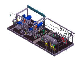
Finite Element Analysis on a Vapor Recovery Unit (VRU) Base Skid to Ensure Structural Integrity to ASME Boiler & Pressure Vessel Code.

For a Client that Manufactures Components for Formula One Race Cars, Engineering Analysis and Design Optimization on Brake Rotor Designs.

Using Finite Element Analysis, an Investigation was performed on a Cracked Heat Exchanger for NASA – including Subsequent Design Modifications.