
Design and Analysis to ASME B&PV and Power & Process Codes
Structural & modal finite element analysis (FEA) of a vapor recovery unit (VRU) base skid was performed to ensure structural integrity.
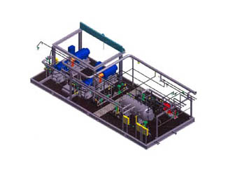
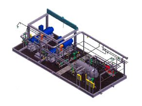
The skid package is used to recover process vapor for use as fuel gas – for a plant near Fort McMurray, Alberta Canada. The equipment included motors, compressors, a separator, heat exchanger, instrumentation and controls, piping and valves, and miscellaneous components. The VRU base skid will also support the utility building in which the system will be located.
The combined VRU Base Skid and Utility Building structure is approximately 55 ft in length, 23 ft in width and 18 ft in height. The VRU Base Skid is a welded steel structure comprising primarily of American Standard W18x50 wide flange beams. The beams are mostly covered with 1/2-inch and 3/4-inch thick steel partially connected (stitch welded in most locations) diamond plating.
An overhead crane with associated support structure interfaces with transverse members of the base skid. The crane can access half of the overall skid, servicing the electric motors and compressors for the VRU system. Design criteria for the base skid structure were obtained in part from the 2006 Alberta Building Code.
We were asked to examine the structural integrity of the base skid supporting the VRU system and the Utility Building based on the customer specification, the 2006 Alberta Building Code/National Building Code of Canada and the Canadian Institute of Steel Construction (CISC) – Handbook for Steel Construction (9th Ed.). Piping is considered in the skid analyses with its weight contribution and other loads it may
apply to the skid (reactions to external loads and thermal loads).
Three-dimensional structural analysis of the VRU base skid was completed for various individual and combined load cases (weight, piping, wind/snow. Resulting axial tensile and compressive forces and stresses, as well as bending stresses from these analyses were compared to corresponding allowable stresses according to the skid design criteria. The final design for the base skid was found to satisfy the specifications and design requirements.
A modal analysis was also performed on the base skid, excluding the piping spools and the building. The response of the skid in the region of the motor/compressor was investigated – in particular, the potential for the electric motor or compressors to excite natural frequencies in the skid structure. No excitable skid modes of vibration were found.
Piping analyses for the VRU Package were also performed, which included various thermal and structural load cases. Design criteria for the piping was obtained from ASME B31.3, Process Piping. This design evaluation method uses stress intensification factors for tees and bends to account for local stress concentrations due to stiffness transitions in the piping system. The Process Piping Code separates the piping loads into two categories: Primary and Secondary. The Primary piping loads include skid displacement, pressure, and deadweight while the Secondary loads include temperature and external nozzle loads.
It was determined from these analyses that additional pipe supports were
needed as well as stiffening of an existing support. The final design was within allowable stress
criteria and satisfied the required specification.
Related Projects
- ASME B31.3 Analysis of a Skid Mounted Heat Transfer System
- ASME B&PV Section VIII Div. 1 Code Analysis of a Feedwater Heater
- Structural & Vibration Analysis of Offshore Skid to ASME Code
- Fatigue Analysis of a Heat Exchanger Coil to ASME Code Section VIII, Div. 2, Part 5
Similar Services
Resources

