
ASME Code Pressure Vessel Design and Analysis
Design and analysis of pressure vessels including Nozzles, (Saddle) Supports and other Appurtenances to ASME B&PV Section VIII Divisions 1, 2 and 3. Analysis includes Finite Element (Stress, Thermal, Seismic / Vibration and Fatigue) Analysis – Ensuring Vessel Structural Integrity.
What is ASME Code?
ASME Boiler and Pressure Vessel (B&PV) codes regulate the design, construction, maintenance and alteration of pressurized equipment. We perform both closed-form Design-By-Formula Methods (ASME Section VIII Division 1) and Design-By-Analysis (ASME Section VIII Division 2) using Finite Element Analysis (FEA).
Why use FEA?
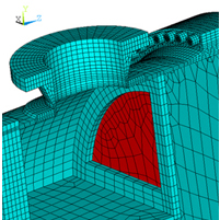
Pressure vessels have wide applications in power plants, as well as the process & chemical industries. Vessels often have openings of various diameters to accommodate manholes, handholds, and nozzles, that develop high stress concentrations which may lead to vessel failure. These geometric discontinuities alter the stress distribution in the neighborhood of discontinuity so that elementary stress equations no longer apply – thus finite element analysis is required.
Why Pressure Vessels Fail — and How ASME Analysis Prevents It
Pressure vessel failures are rarely random. They follow predictable patterns — specific failure modes that develop when design, loading conditions, or material behavior exceed what simplified formulas can adequately characterize. This is precisely why ASME Section VIII Division 2 Part 5 exists: to require explicit, rigorous evaluation of each failure mode rather than relying on conservative thickness margins alone.
O’Donnell Consulting brings uncommon depth to this work. Dr. William O’Donnell was a principal contributor to the fatigue design procedures now embedded in Division 2 and Section III — the same procedures that define how these failure modes are evaluated today. He has written numerous publications on fatigue operating in different temperatures, as well as other failure modes. Understanding not just the code requirements but the engineering judgment behind them is what separates a defensible analysis from one that is formulaic.
The five failure modes Division 2 requires protection against — and how we evaluate each one:
| Failure Mode | What It Is | Typical Triggers | Analysis Method |
|---|---|---|---|
| Plastic Collapse | Progressive, permanent deformation until the vessel can no longer carry load | Excessive internal pressure; overload conditions; inadequate wall thickness | Elastic or elastic-plastic FEA; limit load analysis per Division 2 Part 5.2 |
| Local Failure | Localized rupture at stress concentrations — nozzles, fillets, support attachments — before global collapse occurs | Triaxial stress states at geometric discontinuities; high local strain demand | Elastic stress analysis (principal stress sum limit) or elastic-plastic strain limit analysis per Part 5.3 |
| Buckling | Sudden, catastrophic collapse under compressive or external pressure loading | Vacuum conditions; external pressure; compressive thermal loads; thin-wall vessels | Eigenvalue buckling analysis to find critical modes; elastic-plastic analysis with geometric imperfections per Part 5.4 |
| Fatigue | Crack initiation and propagation from cyclic stress — the most frequent cause of pressure vessel failure in service | Cyclic pressure; thermal cycling; vibration; startup/shutdown cycles; flow-induced loading | Elastic or elastic-plastic fatigue analysis per Part 5.5; fatigue curves developed by Dr. O’Donnell embedded in the ASME Code |
| Ratcheting | Progressive incremental plastic deformation accumulating cycle by cycle until the vessel distorts or fails | Cyclic thermal loads combined with sustained pressure; repeated overloads | Elastic-plastic analysis per Part 5.5.7; shakedown verification to confirm strain stabilization |
Each of these failure modes can be present simultaneously — and in complex vessels with nozzles, thermal gradients, or cyclic operation, all five commonly require evaluation. Design by Analysis using FEA is the only method that can rigorously address all five in a single, integrated model of the actual vessel geometry.
For vessels where simplified Design by Rule cannot adequately characterize the stress state, Design by Analysis is not optional — it is the required path to a code-defensible result.
Examples
- ASME Pressure Vessels
- Process Decanters
- Heat Exchangers
- Cryogenic Vacuum Chambers
- LNG Storage Tanks
- Liquid Oxygen (LOX) Tanks
- Liquid Nitrogen (LIN) Tanks
- Chemical Reactors


Types of Engineering Analysis
- Stress Analysis
- Linear & Non-Linear
- Vibration & Fatigue
- Fitness for Service
- Fracture Analysis
- Design Optimization
- Fabrication Process Evaluation
- Heat Transfer
- Lifting Analysis
- Fatigue Analysis
- Thermal/Transient
- Flow Analysis
- Shock & Impact
- Safety Evaluations
- Elevated Temperature
- Structural Integrity
- Thermal Cycling
- Creep Fatigue
- Creep Ratcheting
- Buckling
ASME Pressure Vessel Codes
- Section III Class 1, 2 and 3 Vessels and Components
- B&PV Section VIII Div. 1, 2 and 3 Vessels
- B&PV Sections IX and XI
