
Contact us: (412) 835-5007 or info@odonnellconsulting.com

Design, Analysis, Troubleshooting & Forensic Engineering
Design, Analysis, Troubleshooting & Forensic Engineering
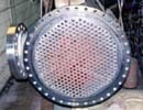
A Number of Cracks were Found around the Bolt Holes of the Inlet and Outlet Tubesheets of a Heat Exchanger in Service at NASA/ Lewis. We Performed Failure Analysis and a Subsequent Redesign to Ensure Conformance to Code.
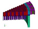
Cracks had initiated at the bolt holes and one extended inwards all the way to the nearest tube hole. Part of the analysis involved determining the stress necessary to cause the cracks at the bolt holes. A detailed three-dimensional (Ansys) model of the tubesheet was made – to be used for both thermal and structural analysis. Due to the symmetry of the tubes in the tubesheets, only a 30-degree segment of each tubesheet was modeled. Sufficient length of the tubes, head and the shell were included in the models to account for their stiffness.
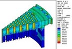
Thermal analysis was performed on the inlet and outlet tubesheets to obtain temperature distributions v. time during heatup and cooldown process. The resulting temperature distributions were used in the structural analysis to determine the corresponding thermal stresses. Structural analysis was then performed to determine stresses in the outlet tubesheets. Three dimensional structural elements were used in the analysis.
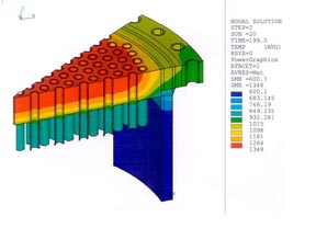
The resulting temperatures at various times in the thermal transient analysis, along with the pressure loads were imposed on the model for stress analysis. The results show that the highest stresses occur at the end of the transient condition.
The analysis showed that the stresses in the circumferential direction are the largest at the tubesheet bolt holes. The maximum stress in the circumferential direction (83.7 ksi) occurs at the bolt hole closest to the outermost tube in the tubesheet. This closely corresponds to the locations of the actual cracks found in the inlet tubesheet. Fatigue analysis at such stress concentrations are best performed using linearized stresses and fatigue strength reduction factors.
The design of the heat exchanger resulted in very high stresses at the boltholes in the tubesheet flange. The material characterization confirmed the existence of plastic straining at the bolt holes, and the cracking was confirmed to be low cycle fatigue. No creep rupture damage voids were found in the grain boundaries. The material away from the high stress cracked areas was considered sound – thus it was concluded that repairs were feasible.
Although the heat exchanger was originally designed and constructed to ASME Section VII Division 1 of the ASME Code, the resulting stresses did not meet the allowable stress limits of the Code. We thus designed modifications for the heat exchanger to meet the Code stress limits.
