
Finite Element Models Simulated the Weld Overlay Process
O’Donnell Consulting Accepted the Challenge to Design a Weld Overlay Process, Proper Welding Sequence, and apply the Overlay while Controlling the Distortion of a Stripper Vessel.
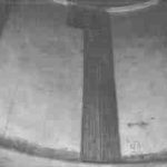
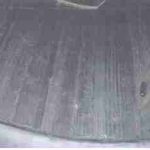
The 9 foot diameter, 60 foot long Stripper Vessel was designed and fabricated for service at a refinery in the Virgin Islands. Prior to starting service, the client wished to cover the top 20 feet of the shell inner surface with Inconel 625 weld overlay to protect the shell base metal against corrosion.
The weld overlay of the vessel required preliminary weld qualifications in accordance with the ASME Code Section IX, Welding and Brazing Qualifications. This dictates the welding of test plates, non-destructive & destructive testing of the test plates, and documentation of all the welding variables and test data. Acceptance criteria for these tests are contained within Section IX and the project specifications (thickness and chemistry requirements). Within Section IX, QW-453, Procedure/Performance Qualification Thickness Limits and Test Specimens For Hard-Facing (Wear-Resistant) and Corrosion-Resistant Overlays define the type and number of tests required.
The welding equipment (used in both the test cases and in the actual overlay) involved a sophisticated Pulse Spray Gas Metal Arc system capable of of capturing a specific welding electronic wave form, and storing it in unique welding schedules.
Temperature measurements were taken on the back side of the test plates for use in the FEA distortion analysis. The measurements were also used for the design of a water cooling system. Bead overlap, weld travel speeds, interpass temperature, and other essential welding variables were adjusted and documented during the test welding, and subsequently incorporated into the final Welding Procedure Specification.
Generally there is less concern regarding vessel distortion when weld overlay is applied on the inner surface of a relatively thick shell. However, in this case, the shell thickness of 5/8” is relatively thin in comparison with the thickness of the weld overlay of 0.17” to 0.20”. Also, the weld metal, Inconel 625, is much stronger and has higher yield strength than the base metal, SA516 Gr. 70.
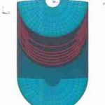
OCE used finite element analysis to design the overlay process with proper welding sequence while controlling the distortion of the vessel.(ANSYS) finite element models were created to:
- simulate the weld overlay process
- obtain the most effective welding sequence for limiting the permanent vessel distortion using simulations of alternative welding sequences.
A three-dimensional model of the entire vessel, including heads, shell, and trays was constructed. 3-D solid elements were used to simulate the vessel. Temperature dependent material properties were used in the analyses. The heads and shell are Carbon Steel and trays are Stainless Steel. The properties of all materials involved were obtained from the ASME Code Section II, Part D.
O’Donnell Consulting Engineers Performs Engineering Analysis – as well as Weld Troubleshooting / Consulting Services.
Related Projects
– Corrosion Investigation on Structures in a Refinery
– Failure Analysis of Ruptured Refinery Bellows
– Cracked Tube to Tubesheet Welds on Chemical Reactor
Similar Services
– Materials/ Metallurgical Consulting
– Engineering Troubleshooting
