
Failure Analysis of Cracked Cylinder Liner On an Engine used to Compress Natural Gas
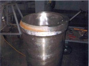
Failure Analysis on a Cracked Cylinder Liner was Performed for a Client that had Manufactured a 18-inch Replacement Cylinder Liner for an Engine used to Compress Natural Gas. During the installation, the new liner cracked and subsequently fell into the engine block – causing damage.
The cylinder sleeve is a centrifugal cast part. The failed cylinder liner had subsequently undergone a design change comprising the incorporation of a larger radius in the location where the shoulder of the liner sits on the engine block. We were asked to perform an analysis on the original and recommend designs. In addition to the finite element analysis, residual stress measurements were performed on a liner with the same design and compared to an OEM liner. The measurements were also used to determine if the heat treatment or machining processing could have had an impact on the liner failure.
These measurements, along with finite element analysis using measured nonlinear cylinder liner material properties from testing were completed as part of the second phase of the failure investigation. Metallography and fractography was also performed to characterize the failure and determine if material anomalies contributed to the fracture.
Finite Element Analysis
The following assumptions were used in the modeling of the liner.
- The assembly from bottom to top is the following: engine block with 8 studs, cylinder liner, gasket, cylinder head, and nuts. The cylinder liner sits on the block, and is held in place by the compression of the tightened nuts on the cylinder head.
- The eight 2-inch studs/nuts are torqued to 1400 ft-lbs each.
- The cylinder liner is made of gray cast iron material, with a room temperature tensile strength of at least 40 ksi (275 MPa)
- Four analyses were completed using two models:
(i) The first analysis was based on a model with a cylinder shoulder with a 0.031 inch radius held along the full width of the entire horizontal shoulder surface where the engine block is in contact with the cylinder.
(ii) The second analysis used the same model but was held on the outer half of the horizontal shoulder surface. A 0.375-inch radius was used to represent the newer cylinder design for the second model and third analysis.
(iii) The fourth analysis used the larger radius but was held at the outer half of the horizontal shoulder surface. - The liner had a zero displacement constraint in the vertical direction on the horizontal shoulder surface where it sits on the engine block.
Analysis Results
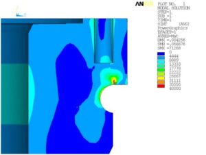
Stresses over 40 ksi were found in all the load cases with the smallest regions occurring in the new design with full shoulder constraints. The smaller radius concentrates the stresses in this region causing higher stresses in the original design than the new design. The maximum overall stress occurred in the hole region for the original design with full shoulder constraints.
The finite element results did not conclusively indicate the cause of the fracture in the cylinder liner. High stresses in both models at the edge of the radius and hole location in conjunction with other factors could be sufficient to cause a fracture. Fracture mechanics analyses would allow comparison of the applied stress intensity with the critical stress intensity for an assumed flaw size.
The fracture appears to be a combination of Mode I (tensile) and Mode II (shear) fracture and can be treated using linear elastic fracture mechanics. A detailed metallurgical examination was recommended to identify the initial fracture location, confirm material integrity, and rule out other potential factors, which could result in a fracture of this kind.
For over 30 Years, O’Donnell Consulting has been performing Failure Analysis of Equipment.
Related Projects
- Failure Analysis & Redesign on Fracking Pump
- Failure Analysis & Redesign on a Threaded Joint Casing
- Failure Analysis on a Cement Kiln
Similar Services
Resources

